
You’ve probably watched your pet stare at their empty bowl with those pleading eyes while you’re stuck at work, wishing you could feed them remotely. Converting a basic pet feeder with Tasmota firmware transforms it into a smart, controllable device that responds to your commands from anywhere. The process involves flashing ESP chips, configuring MQTT protocols, and integrating motion sensors—but there’s a critical step most guides won’t warn you about.
Hardware Requirements and Prerequisites
Before diving into the firmware flashing process, you’ll need to gather the essential hardware components for your Tasmota-powered pet feeder project.
Your main controller should be an ESP device compatible with ESP8266, ESP8285, ESP32, ESP32-S, or ESP32-C3 chipsets. You’ll also need a reliable serial programmer like CH340G, CP2102, or NodeMCU for flashing the firmware onto your ESP device.
Make sure it provides sufficient 3.3V power to avoid damaging the chip. Install the appropriate drivers for your serial programmer beforehand.
Additionally, gather basic soldering tools and jumper wires for connecting components. Remember to connect the serial-to-USB converter’s TX and RX pins to your ESP’s corresponding RX and TX pins respectively.
Preparing the ESP Device for Flashing
Before you can flash Tasmota firmware onto your pet feeder’s ESP device, you’ll need to verify that your hardware components are compatible and properly assembled.
Start by confirming you have an ESP8266, ESP8285, or ESP32 along with a serial programmer like CH340G or CP2102.
Next, you’ll establish the serial connections between your programmer and ESP device, ensuring proper voltage levels and data line configuration for successful firmware installation.
Hardware Requirements Check
The hardware-compatibility checkpoint serves as your foundation for successful Tasmota installation on pet feeder devices.
You’ll need to verify your ESP8266 chip or ESP32 module compatibility before proceeding with the firmware modification process.
Essential components for successful installation:
- Compatible ESP Device – ESP8266 or ESP32 microcontroller within your pet feeder’s circuit board
- Serial Programmer – CH340G or CP2102N adapter providing stable 3.3V power output to protect your chip
- Proper Wiring Setup – TX/RX pin connections between programmer and ESP, plus 3.3V and GND connections
- Programming Mode Access – GPIO0 pin availability for grounding during boot sequence
Double-check all connections before you flash the firmware, as incorrect wiring can permanently damage your pet feeder’s electronics and prevent successful Tasmota installation.
Serial Connection Setup
Serial connection accuracy determines whether your Tasmota firmware flash succeeds or fails catastrophically.
You’ll need to connect your serial-to-USB converter’s TX pin to the ESP chip’s RX pin, and RX to TX respectively. Don’t forget the 3.3V and GND connections for proper power supply.
Before powering on, connect GPIO0 to GND to enable programming mode—this step’s absolutely critical.
Verify your serial programmer outputs 3.3V, not 5V, which would damage your ESP chip. Use a USB data cable that actually transfers data; charging-only cables won’t work.
Double-check every wire connection and solder joint against your device’s pinout documentation.
Open your serial terminal software and confirm communication before proceeding with the Tasmota flash.
Installing Required Software Tools
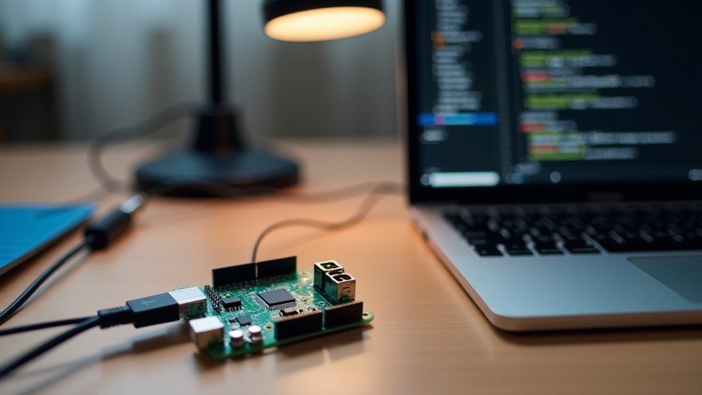
When preparing to flash Tasmota firmware onto your pet feeder’s ESP device, you’ll need to install several essential software tools on your computer.
Python is crucial since it’s required for running esptool, the primary flashing utility. The installation process involves several key steps:
Python serves as the foundation for esptool functionality, making it an indispensable prerequisite for successful firmware flashing operations.
- Install Python – Download and install the latest Python version from python.org, guaranteeing it’s added to your system PATH.
- Install esptool – Open your terminal or command prompt and run `pip install esptool` to get the flashing tool.
- Download Tasmota firmware – Get the appropriate tasmota.bin file from the official Tasmota release page.
- Prepare USB cable – Ascertain you have a reliable USB data cable that supports data transfer, not just charging.
Serial Connection Setup and Wiring
You’ll need specific hardware components to establish a proper serial connection with your pet feeder’s ESP device.
The programming mode configuration requires precise wiring between your serial adapter and the ESP board to enable firmware flashing.
Let’s examine the essential components and wiring setup needed to prepare your device for Tasmota installation.
Essential Hardware Components
Before you can flash Tasmota firmware onto your pet feeder’s ESP device, you’ll need to establish a proper serial connection through careful wiring.
Getting the hardware components right guarantees smooth firmware binary installation without damaging your device.
You’ll need these essential components for a successful connection:
- Serial programmer – A USB-to-TTL adapter that provides 3.3V output and adequate current delivery
- Jumper wires – Quality connecting wires to link your serial adapter’s pins to the ESP device
- Reliable 3.3V power supply – Never use 5V as it’ll damage the ESP chip permanently
- Programming button or jumper – To connect GPIO0 to GND for entering programming mode
Double-check all connections before powering up to avoid flashing issues.
Programming Mode Configuration
Two critical steps determine whether your ESP device successfully enters programming mode: establishing the correct serial connection and triggering the boot sequence properly.
You’ll need to wire your serial programmer correctly by connecting the adapter’s 3V3 to ESP’s 3V3, GND to GND, TX to RX, and RX to TX. Verify your serial programmer outputs 3.3V—5V will damage your ESP chip.
Use a USB data cable that supports transmission; charging-only cables won’t work with your programming interface.
To enter programming mode, connect GPIO0 to GND during boot using a button or jumper wire. Always double-check connections before flashing and use esptool.py to verify your device communicates properly with the programming interface.
Entering Programming Mode

Getting your ESP device into programming mode requires connecting the GPIO0 pin to ground (GND) during the boot-up sequence. This connection tells your device to accept new firmware instead of running its current program.
Here’s how to enter programming mode effectively:
- Power down your ESP device completely and disconnect any existing power sources.
- Connect GPIO0 to GND using either an onboard button (if available) or a jumper wire bridge.
- Power up the device while maintaining the GPIO0 connection to guarantee proper mode activation.
- Verify programming mode by running esptool.py to confirm your device’s connection status.
Keep that GPIO0 connection active throughout the entire flashing process.
Your serial programmer’s TX and RX pins must align correctly with your ESP device for successful communication.
Backup and Firmware Flashing Process
Before you flash Tasmota onto your pet feeder’s ESP device, you’ll need to create a backup of the original firmware to protect against potential issues.
Once you’ve secured your backup, you can erase the existing flash memory and install the Tasmota binary file.
This process transforms your device into a fully customizable smart feeder that you can control remotely.
Creating Firmware Backups
Protect your pet feeder’s original functionality by creating a complete firmware backup before attempting any modifications.
You’ll need to identify your device’s COM port and guarantee you have proper access permissions for the backup process.
Execute the backup command to save your current firmware:
- Connect your device – Verify it’s properly connected to COM5 (or your specific port)
- Run the backup command – Use `esptool.py –port COM5 read_flash 0x00000 0x100000 fwbackup.bin`
- Wait for completion – The process will read the entire flash memory contents
- Verify the backup file – Check that `fwbackup.bin` was created successfully
This firmware backup serves as your safety net, allowing you to restore original functionality if issues arise during Tasmota installation.
Flashing Tasmota Binary
Three critical steps transform your pet feeder from factory firmware to Tasmota control.
First, you’ll erase the existing flash memory using `esptool.py –port COM5 erase_flash` to prepare for installation. This command completely wipes the current firmware, creating a clean slate for flashing Tasmota binary.
Next, upload your precompiled binary with `esptool.py write_flash -fm dout 0x0 tasmota.bin`, ensuring you specify the correct file path. The `-fm dout` parameter configures the flash mode for best compatibility with ESP devices.
Remember that your device must remain in Programming Mode throughout this process—GPIO0 connected to GND during boot is essential.
Once flashing completes successfully, you can disconnect GPIO0 and reboot to access Tasmota’s configuration interface.
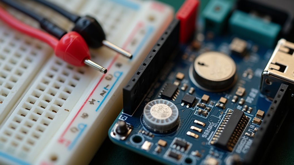
Pet Feeder Circuit Design and Components
The heart of your automated pet feeder lies in a carefully orchestrated circuit that combines an ESP12F module with specialized components to create a reliable feeding system.
This ESP-powered Smart Home device integrates seamlessly with Tasmota firmware to deliver precise feeding control.
Your circuit design incorporates these essential components:
- ULN2003 driver circuit – Controls the stepper motor for accurate food dispensing portions
- Dual power supply system – 5V for motor operations and 3.3V for ESP12F and sensors
- PIR motion sensor – Detects nearby pets and triggers manual feeding notifications
- Buzzer alert mechanism – Announces meal times to guarantee pets know food’s available
This configuration guarantees your ESP12F manages all operations efficiently while maintaining component safety through proper voltage distribution across the feeding system.
Configuring WiFi Network Settings
Once you’ve successfully flashed Tasmota firmware onto your ESP12F module, you’ll need to establish WiFi connectivity to integrate your pet feeder into your smart home network.
After flashing, your device creates a temporary access point named “tasmota_XXXXXX-####” that’ll appear in your Wi-Fi network list. Connect to this access point and navigate to the IP address http://192.168.4.1 to access the configuration page.
Enter your home network’s SSID and password, ensuring the password doesn’t exceed 64 characters and contains no special characters or spaces. Click “Save” to connect the device to your network.
Upon successful connection, you’ll see a new IP address. If connection fails, the configuration screen reappears for troubleshooting.
Setting Up MQTT Communication
Now that your pet feeder’s connected to WiFi, you’ll need to establish MQTT communication for remote control and monitoring.
You’ll start by configuring your MQTT broker settings, then plan your topic structure to organize device messages effectively.
Finally, you’ll set up the proper message formats to guarantee your commands and status updates transmit correctly between your feeder and control devices.
MQTT Broker Configuration
Before your Tasmota pet feeder can communicate with other smart devices, you’ll need to establish MQTT communication by configuring the broker settings.
Navigate to your Tasmota web interface and access the Configuration menu, then select “Configure MQTT.”
Here’s how to set up your mqtt broker connection:
- Enter your broker’s IP address and port number (typically 1883) in the designated fields.
- Create a unique MQTT Topic that identifies your pet feeder for message publishing and subscribing.
- Input authentication credentials if your broker requires a username and password for secure access.
- Enable auto-discovery features using the Backlog command to guarantee seamless Home Assistant integration.
Test your configuration using MQTT client tools like MQTT Explorer to verify successful communication.
Topic Structure Planning
With your MQTT broker configured, you’ll need a well-structured topic hierarchy to organize communication between your pet feeder and other smart home devices.
Design your MQTT topic structure using the format “petfeeder/{device_name}” to guarantee uniqueness and prevent conflicts with other connected devices. This naming convention helps maintain clear organization when managing multiple feeders or shifting between different Tasmota firmware versions.
Create distinctive device names within your Tasmota firmware settings that reflect each feeder’s location or purpose, such as “petfeeder/kitchen” or “petfeeder/mainfloor.”
Consider implementing subtopics for specific functions like “petfeeder/kitchen/status” for device health monitoring and “petfeeder/kitchen/feed” for dispensing commands.
This hierarchical approach simplifies automation rules and troubleshooting while maintaining scalable communication protocols for future smart home expansions.
Message Format Setup
After establishing your topic hierarchy, you’ll need to configure the actual message formats that your pet feeder will send and receive through MQTT.
Your Tasmota pet feeder will communicate using JSON payloads that contain essential operational data.
Configure these critical message formats:
- Status messages – Include power supply voltage, feeding completion status, and motor health indicators
- Command responses – Acknowledge received feeding instructions with timestamp and execution confirmation
- Error notifications – Report low food levels, power supply issues, or mechanical failures with specific error codes
- Heartbeat signals – Send periodic alive messages containing device name and system uptime
Use the Backlog command to set your device name and enable structured messaging.
Your Home Assistant integration will parse these JSON messages automatically, ensuring reliable communication between your pet feeder and smart home system.
Stepper Motor Control Configuration
Once you’ve installed Tasmota firmware on your pet feeder’s ESP module, you’ll need to configure the stepper motor control settings to manage the dispensing mechanism.
Begin by accessing your device configuration and defining the GPIO pin assignments for your ULN2003 driver circuit connections. Set the number of steps per revolution according to your stepper motor’s specifications.
Use Tasmota’s command interface to control the motor with `MotorMove` commands, specifying step count and direction parameters for clockwise or counterclockwise rotation. This enables precise portion control during feeding cycles.
Configure automated timers within Tasmota to execute motor commands at scheduled intervals.
Ascertain your power supply provides adequate voltage – typically 5V for the stepper motor while maintaining 3.3V for the ESP module to prevent operational damage.
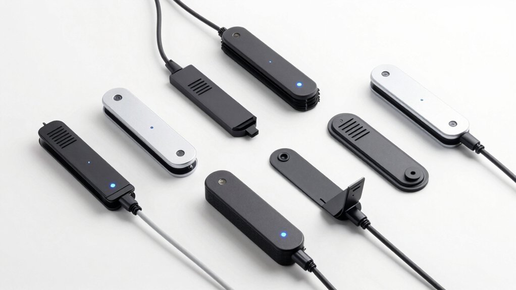
PIR Sensor Integration and Detection
Building on your automated feeding schedule, you can enhance your pet feeder’s intelligence by integrating a PIR (Passive Infrared) sensor that detects your pet’s presence before dispensing food.
This PIR sensor provides basic functionality by monitoring infrared radiation changes when your pet approaches the feeding area.
The sensor’s detection capabilities transform your feeder into a responsive system:
- Motion Detection Range: Your PIR sensor covers 6-12 meters, effectively monitoring various room sizes where pets roam and approach their feeding station.
- Voltage Compatibility: Operating between 3.3V-5V guarantees seamless integration with your ESP module while maintaining efficient power consumption.
- Automatic Activation: When triggered, the sensor immediately notifies your ESP module to activate the dispensing mechanism.
- Waste Reduction: Food dispenses only when pets are detected nearby, preventing unnecessary waste and guaranteeing fresh meals.
Home Assistant Integration Setup
While your PIR sensor creates intelligent detection capabilities, integrating your Tasmota-powered pet feeder with Home Assistant opens extensive automation and monitoring features that transform basic feeding into a sophisticated smart home experience.
First, configure your MQTT broker in Tasmota by entering the correct IP address, port, username, and password in the device settings.
Next, access Home Assistant’s Configuration section and add your Tasmota device using its unique topic and feeding control parameters.
Create custom automations for scheduled feedings and status alerts through MQTT messages.
Use Developer Tools to test motor control and buzzer services, ensuring seamless communication.
Finally, add a dashboard button entity for manual feeding control, giving you instant access to your pet feeder’s functionality from Home Assistant’s interface.
Automated Feeding Schedule Programming
Since your Home Assistant integration provides the foundation for smart control, programming automated feeding schedules through Tasmota’s web interface becomes your next essential step toward establishing consistent meal routines for your pets.
Your automated feeding schedule can be programmed using Tasmota firmware through these steps:
- Access Tasmota’s web interface to configure multiple daily feeding times based on your pet’s dietary requirements.
- Set precise portion controls for each scheduled feeding session to maintain healthy eating habits.
- Activate MQTT communication for remote schedule modifications through your smartphone or smart home system.
- Configure PIR sensor notifications to receive real-time alerts when your pet approaches the feeder.
You’ll modify schedules directly through the interface without reflashing firmware, while MQTT support guarantees seamless integration with mobile applications for convenient remote management.
Testing and Troubleshooting Your Pet Feeder
How can you guarantee your Tasmanta-powered pet feeder operates reliably after completing the automated scheduling setup?
Start by ensuring your ESP device receives adequate power and connects properly to the serial programmer. Set the correct baud rate in your terminal software before issuing the following command: `status` to verify Wi-Fi connectivity and operational status.
If food doesn’t dispense on schedule, check motor connections and confirm your stepper motor receives proper 5V voltage.
Test PIR sensor functionality by triggering it manually and adjusting sensitivity settings as needed.
Access Tasmota’s web interface to verify MQTT broker configuration – incorrect credentials prevent Home Assistant communication.
Monitor device responses carefully during testing to identify potential issues before deploying your automated feeding system.
Frequently Asked Questions
What Is Tasmotizer?
Tasmotizer’s a GUI tool that simplifies flashing Tasmota firmware onto ESP devices. You’ll select firmware files and serial ports easily, while it automatically handles erasing flash and writing firmware with progress updates.
How Do You Enter Pairing Mode on Tasmota?
You’ll enter pairing mode by connecting GPIO0 to GND during boot. Keep this connection throughout flashing. Use a serial-to-USB adapter and confirm programming mode with esptool.py before uploading firmware.
What Is the Default Password for Tasmota Admin?
The default password for Tasmota admin access is “admin.” You’ll want to change this immediately during initial setup to secure your device, since keeping default credentials makes your system vulnerable to unauthorized access.
Why Is My Tasmota Not Connecting to WIFI?
Check you’ve entered a valid Wi-Fi password under 64 characters without special characters. Make certain you’re within router range, GPIO0 isn’t grounded during boot, and you’ve flashed correct firmware.

Leave a Reply