You’re probably tired of fumbling for light switches in dark rooms or wondering if you left that lamp on while you’re away from home. Z-Wave outlets offer a straightforward solution that transforms ordinary electrical outlets into smart, controllable power sources. While the installation process might seem intimidating at first glance, replacing a standard outlet with a Z-Wave version is surprisingly manageable for most homeowners. However, there’s one critical step that determines whether your installation succeeds or creates costly problems.
Safety Preparation and Circuit Breaker Shutdown
Before you begin installing your Z-Wave outlet, you must shut off power at the circuit breaker or fuse box to prevent electrical shock.
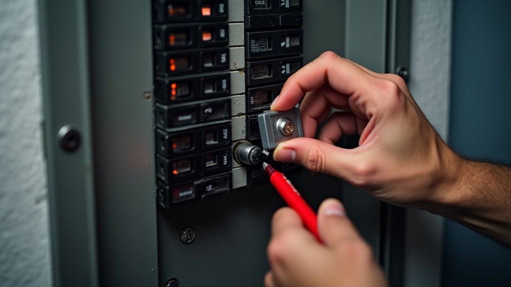
First, identify the correct circuit breaker for the outlet you’re replacing by testing the existing outlet to confirm it’s powered off. Once you’ve located the right breaker, switch it to the off position.
Next, use a voltage tester to verify there’s no electrical current present in the outlet before handling any wiring. This critical step guarantees your safety throughout the installation process.
While you’re preparing, label the wires connected to the existing outlet to avoid confusion during installation.
Always follow local electrical codes and safety regulations to guarantee compliance and maintain safety standards throughout your Z-Wave outlet installation project.
Removing the Existing Outlet and Wallplate
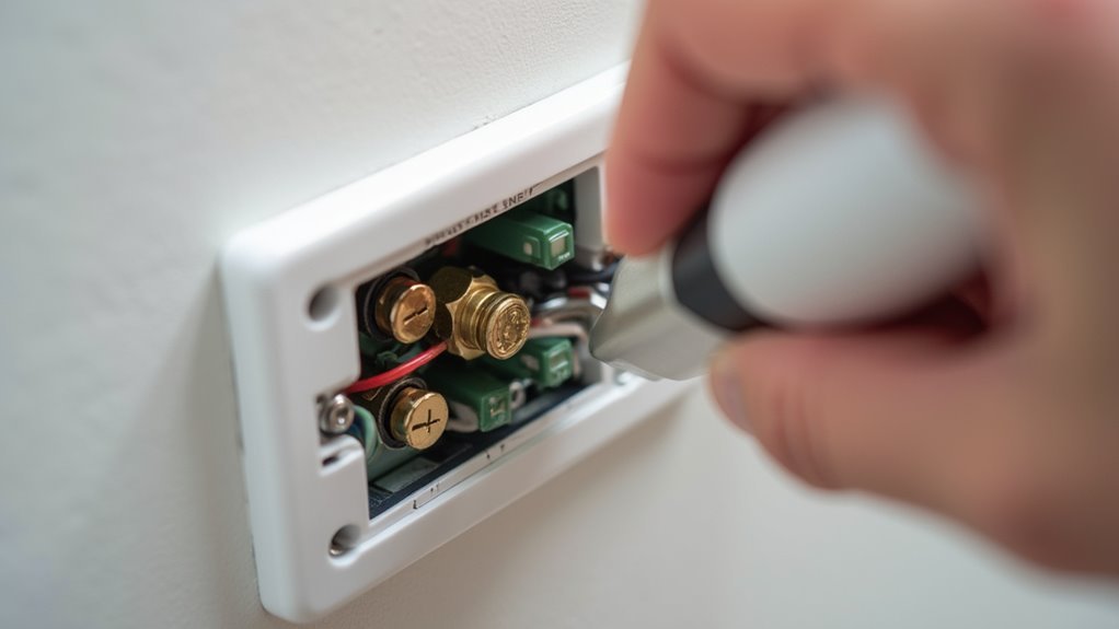
With the power confirmed off and your safety measures in place, you can now remove the existing outlet. Start by using a screwdriver to unscrew the mounting screws that secure the wallplate covering the outlet.
Once you’ve removed the wallplate, you’ll see the outlet itself mounted within the electrical box.
Next, carefully unscrew the outlet from the electrical box to access the wiring connections behind it. Before disconnecting anything, take a moment to label each wire according to its function—LINE, NEUTRAL, and GROUND. This labeling will guarantee proper reconnection later during installation.
After labeling, disconnect the wires from the existing outlet terminals. Finally, safely remove the outlet from the electrical box, making sure no exposed wires touch each other.
Wire Identification and Labeling Process

Before you disconnect any wires from the old outlet, you’ll need to identify and document each wire’s function using the standard color coding system.
Take a moment to label the black wire as LINE (hot), the white wire as NEUTRAL, and the green or bare wire as GROUND using electrical tape or a permanent marker.
This documentation step prevents confusion when you’re ready to connect the wires to your new Z-Wave outlet’s terminals.
Proper Wire Color Coding
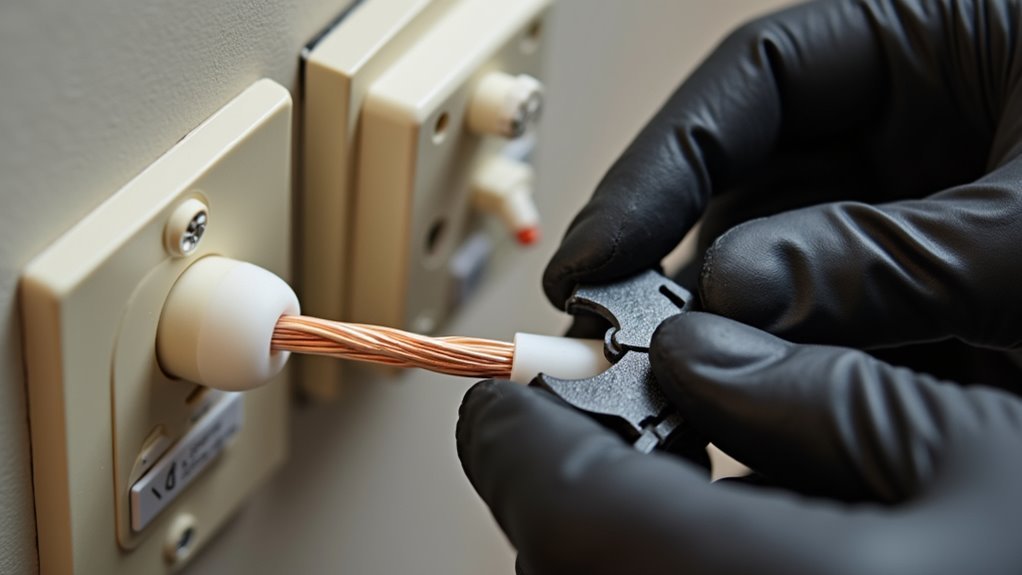
Identifying and labeling your electrical wires correctly forms the foundation of a safe Z-Wave outlet installation. In standard wiring, you’ll find black wires serving as hot (LINE) connections, white wires functioning as neutral, and bare or green wires designated for ground. However, don’t assume these colors always follow convention.
Before disconnecting your existing outlet, label each wire according to its actual function rather than color alone. Use masking tape to mark LINE, NEUTRAL, and GROUND on respective wires. Strip exactly 5/8 inch (16 mm) from each wire end for ideal terminal contact.
Verify you’re working with 14 AWG or larger wires to meet safety standards for your smart outlet. Always reference the manufacturer’s wiring diagram to confirm proper connections, especially when dealing with non-standard color coding.
Documentation Before Disconnection
Once you’ve confirmed proper wire identification, creating a detailed record becomes your next critical step before touching any connections.
Label each wire connected to the existing outlet with tape or a marker, clearly marking LINE, NEUTRAL, and GROUND to avoid confusion during installation.
Taking a photo of the current wiring setup provides an invaluable reference point that’ll help clarify uncertainties when connecting your new Z-Wave outlet.
These documentation steps prevent dangerous mix-ups and guarantee you’ll reconnect everything correctly.
Before disconnecting anything, double-check that you’ve shut off power at the circuit breaker.
This systematic approach to documentation transforms what could be a confusing process into a straightforward, safe installation.
Understanding Line, Load, and Neutral Connections
When installing Z-Wave outlets, you’ll encounter three essential wire connections that determine whether your smart device functions properly: LINE, LOAD, and NEUTRAL.
The LINE wire brings hot power from your electrical panel to the outlet, typically colored black. You’ll identify the LOAD wire as it carries power from switches to controlled devices—also potentially black, making proper identification vital.
The NEUTRAL wire, usually white, completes your circuit by returning current to the panel. Smart outlets require all three line, load, and neutral connections for proper operation.
Misidentifying these wires can bypass switch functionality, leave outlets unexpectedly hot, or render your Z-Wave device completely inoperable, creating safety hazards.
Proper Wire Stripping and Connection Techniques
You’ll need to strip your wires to the exact 5/8-inch length to guarantee they connect properly to the Z-Wave outlet’s terminals.
Make sure you’re using 14 AWG or larger copper wires, as smaller gauges won’t handle the electrical load safely.
Focus on matching each wire to its correct terminal—LINE to A, NEUTRAL to B, and GROUND to C—then tighten the screws to 14 Kgf-cm for a secure connection.
Recommended Strip Length Guidelines
Proper wire preparation forms the foundation of a secure Z-Wave outlet installation, and the Resideo Z5OUTLET requires precisely 5/8 inches (16 mm) of stripped wire for optimal terminal connections. Following recommended strip length guidelines guarantees your smart outlet functions reliably and safely.
When preparing wires for your Z-Wave outlet installation, you’ll need to maintain specific standards:
- Strip exactly 5/8 inches of insulation from each wire end to match the terminal depth requirements
- Use only 14 AWG or larger copper wires to meet safety regulations and guarantee peak performance
- Apply 14 Kgf-cm (12 lbf-in) of torque when tightening terminal screws to secure connections without damaging components
Consistent adherence to these measurements prevents loose connections that could cause intermittent operation or safety hazards in your smart outlet installation.
Proper Terminal Connection Methods
Three critical steps guarantee your Z-Wave outlet connections remain secure and code-compliant throughout the installation process.
First, you’ll connect your labeled wires to the designated terminals on your smart outlets. Attach the LINE (Hot) wire to terminal A, the NEUTRAL wire to terminal B, and the GROUND wire to terminal C. Ascertain each wire fits securely into its respective terminal before proceeding.
Next, you’ll tighten each terminal screw to exactly 14 Kgf-cm (12 lbf-in) of torque. This precise measurement prevents loose connections that could cause arcing or overheating. Under-tightening creates safety hazards, while over-tightening can damage the terminal or strip the threads.
Finally, verify that your 14 AWG or larger wires maintain their 5/8 inch strip length and sit flush against the terminal contacts.
Wire Gauge Requirements
Wire gauge selection forms the foundation of safe Z-Wave outlet installations, with 14 AWG copper wire serving as the minimum requirement for these smart devices.
You’ll need to verify your existing wiring meets this specification before proceeding with installation. Using undersized wires can create dangerous conditions and prevent proper device operation.
When preparing your connections, follow these essential requirements:
- Strip exactly 5/8 inches (16 mm) of insulation from each wire end for ideal terminal contact
- Use only copper wire materials, as other wire types aren’t compatible with Z-Wave outlets
- Apply 14 Kgf-cm (12 lbf-in) tightening torque to screw terminals for secure connections
Before you begin, label your existing wires to maintain proper identification.
Once you’ve got all wires connected according to these specifications, your Z-Wave outlet will operate safely and efficiently.
Installing the Z-Wave Smart Outlet Device
Before you begin installing your Resideo Z5OUTLET Z-Wave Plus In-Wall Outlet, shut off power at the circuit breaker or fuse box to guarantee your safety throughout the installation process.
Remove the existing wall plate and outlet mounting screws, then carefully disconnect the wires while labeling them for easy identification during reconnection.
Label your wires during disconnection to ensure proper reconnection and avoid confusion during the Z-Wave outlet installation process.
Match your labeled wires to the appropriate screw terminals on the Z-Wave In-Wall Outlet: connect the hot wire to LINE, neutral wire to NEUTRAL, and ground wire to GROUND.
Secure the outlet in the box with screws and mount the wall plate.
Restore power and pair the outlet with your Z-Wave controller for remote operation. The outlet supports 1800W maximum load and includes LED indicators for dark visibility.
Securing the Outlet and Mounting Hardware
After connecting all the wires to their designated terminals, you’ll need to carefully position the Z-Wave outlet into the electrical box, guaranteeing the outlet face sits flush against the wall surface with no visible gaps.
Proper positioning prevents electrical hazards and guarantees professional installation results.
Next, secure the outlet to the outlet box using the provided screws. Apply the recommended tightening torque of 14 Kgf-cm (12 lbf-in) to guarantee reliable mounting without overtightening.
Key installation steps:
- Check wire connections – Verify all LINE, NEUTRAL, and GROUND wires are tightly connected with no exposed conductors
- Secure mounting screws – Fasten the outlet firmly to the outlet box using proper torque specifications
- Install wallplate – Reattach the cover plate, guaranteeing it fits snugly without loose ends
Power Restoration and Initial Testing
After securing your Z-Wave outlet in place, you’ll need to restore power at the circuit breaker to begin the testing phase.
Once power’s restored, check that the blue LED indicator lights up to confirm the outlet’s receiving electricity and functioning properly.
You can then test both the manual program button and remote Z-Wave controller functionality to guarantee everything’s working as intended.
Restore Circuit Power
Once you’ve securely connected all wires and installed the Z-Wave outlet, it’s time to restore power to the circuit.
Head to your electrical panel and flip the circuit breaker back to the “on” position. This step brings electricity back to your newly installed smart switch and allows you to begin testing its functionality.
Before proceeding with any testing, you’ll want to verify everything’s working safely and correctly:
- Use a non-contact voltage tester to confirm power is present at the outlet
- Check that the blue LED indicator illuminates, showing the device is receiving power
- Press the front program button to test manual on/off operation
Successfully completing these steps means you can restore circuit power confidently and move forward with pairing your outlet to a Z-Wave controller.
Test Outlet Function
Testing your newly installed Z-Wave outlet requires three essential verification steps to guarantee proper functionality and safety.
First, restore power at the circuit breaker to activate your outlet with a smart connection capability. Press the manual ON/OFF control button on the front to test immediate functionality. You’ll see the blue LED indicator illuminate, confirming it’s receiving power and can be easily located in darkness.
Next, verify load capacity limits don’t exceed 960W for incandescent or 1800W for 15A resistive loads, as exceeding these thresholds causes malfunctions.
Finally, test remote control capabilities by connecting to your Z-Wave controller. Attempt turning the outlet on and off through the controller interface to confirm wireless communication works properly before completing installation.
Z-Wave Network Pairing and Setup
Before you can control your Resideo Z5OUTLET through your smart home system, you’ll need to pair it with your Z-Wave network. The pairing process is straightforward when you follow the proper steps.
Ensure your outlet is powered on and positioned within range of your Z-Wave controller before starting. Press the front program button to activate inclusion mode, then follow your Z-Wave Smart controller’s specific pairing instructions. Watch for the blue LED indicator to confirm successful pairing.
Key pairing tips:
- Keep the outlet close to your controller during setup to avoid communication issues
- Press the program button firmly and wait for your controller to detect the device
- Configure outlet settings afterward using Z-Wave configuration commands for customized LED behavior and load preferences
Configuring LED Indicators and Parameters
After successfully pairing your Z5OUTLET with your Z-Wave network, you’ll want to customize the LED indicator settings to match your preferences and lighting needs.
The Z5OUTLET features a blue LED that helps you locate the outlet in dark environments. You’ll need to use your Z-Wave controller to configure Parameter 31, which offers three options: LED ON/Device OFF (0), LED ON/Device ON (1), or completely disable the LED (2).
These LED indicators provide visual feedback about your outlet’s operational state, making control more intuitive. Your Z-Wave controller must support configuration command class to adjust these settings properly.
The outlet handles up to 960W for incandescent bulbs and 1800W for resistive loads while maintaining LED functionality for enhanced user interaction.
Troubleshooting Common Installation Issues
Three common issues can derail your Z-Wave outlet installation: improper wiring connections, power supply problems, and network pairing failures.
Most troubleshooting starts with verifying your electrical box connections and guaranteeing power flows correctly through your circuit.
When your outlet remains hot despite switch position changes, you’ve likely connected the LINE wire incorrectly.
Double-check that you’ve labeled and connected the hot, neutral, and ground wires to their proper terminals. If your electrical box lacks adequate space or contains complicated split-outlet wiring, consult an electrician immediately.
- Verify circuit breaker: Confirm power’s completely off before troubleshooting any wiring issues
- Check wire connections: Confirm LINE, NEUTRAL, and GROUND wires match outlet requirements
- Test switch functionality: Confirm the outlet responds properly to switch commands after installation
Frequently Asked Questions
Can Z-Wave Outlets Work Without a Neutral Wire in Older Homes?
You can’t use standard Z-Wave outlets without a neutral wire in older homes. You’ll need special no-neutral Z-Wave switches instead, or hire an electrician to run new wiring with neutral conductors.
What’s the Maximum Distance Between Z-Wave Outlets for Reliable Mesh Networking?
You’ll get reliable mesh networking between Z-wave outlets when they’re within 30-100 feet of each other, depending on your home’s construction materials. Thick walls and metal reduce range considerably.
Do Z-Wave Outlets Require a Specific Hub or Work With Any Brand?
You’ll need a compatible Z-Wave hub since outlets don’t work with every brand. Check your hub’s compatibility list before buying. Most major brands like SmartThings, Hubitat, and Vera support standard Z-Wave outlets.
Will Installing Z-Wave Outlets Void My Home’s Electrical Warranty or Insurance?
Installing Z-wave outlets typically won’t void your electrical warranty if you’re replacing existing outlets with proper permits. However, you should check your specific warranty terms and notify your insurance company about smart home additions.
Can Z-Wave Outlets Be Installed in Outdoor Weatherproof Electrical Boxes Safely?
You can install z-wave outlets in outdoor weatherproof boxes if they’re rated for outdoor use. Look for NEMA-rated enclosures and guarantee proper GFCI protection. Check manufacturer specifications for temperature ranges and moisture resistance before installation.

Leave a Reply